S.A.T. Instruction Manual
* DO NOT ATTACH THE S.A.T. TO YOUR YAESU ROTATOR UNTIL YOU COMPLETE THE CALIBRATION STEPS DESCRIBED BELOW
Introduction
The S.A.T. is a novel and completely self contained device used to predict and track satellite passes while simultaneously controlling an antenna rotator and tuning a transceiver. Once connected to mobile device or computer through it's built it WiFi, all control is performed through any web browser.Get Familiar
LCD
The built in LCD displays information depending on the state of the S.A.T. For example, the IP address, serial number and firmware version are displayed when the S.A.T. is idle. When actively tracking, the satellite name, azimuth, elevation, range and range rate and AOS/LOS is shown. Other status message are also available such as during TLE and firmware updates.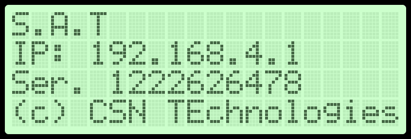
PORTS
The ports for connecting power, the rotator and your radio are location along to the top of the S.A.T. Use the guide to identify the various connections.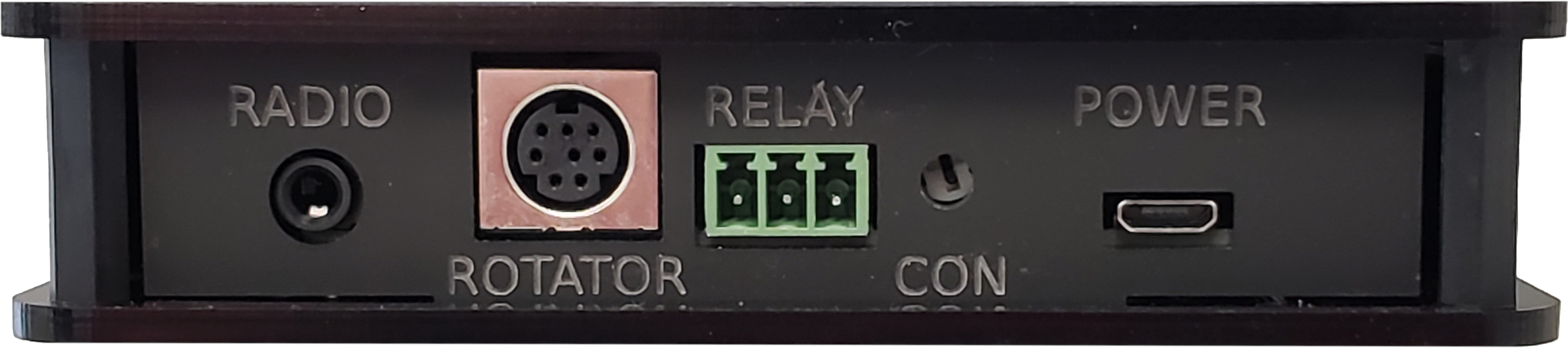
RADIO CI-V CONNECTION
The RIG CONTROL port on your S.A.T. plugs into your radio with the provided Tip-Ring-Sleve cable. Refer to the images on the right to find the CI-V or Remote jack on your radio. The correct jack has been highlighted in violet.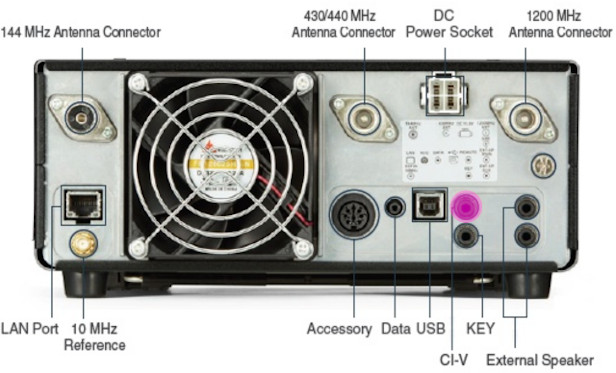
Icom IC-9700
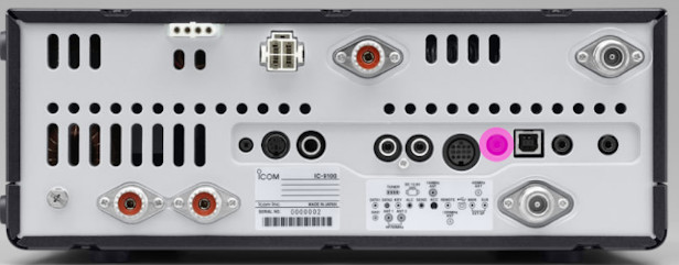
Icom IC-9100
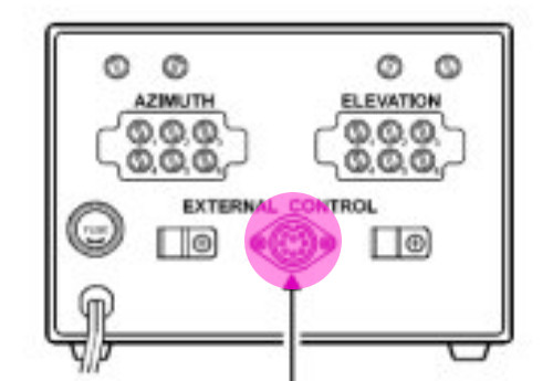
ROTATOR CONNECTION
Plug the Mini-DIN connector into the S.A.T. and the full size DIN connector to the back of the rotator control box. Refer to the image for the correct port.* Do not connect the rotator until you read the calibration procedure below.
Apply Power and Boot
Attach USB
Your S.A.T. is powered by 5V through any standard USB port. Using the provided Micro-USB cable, attached your S.A.T. to a USB port. Since the S.A.T. is an extremely low power device, almost any USB power source will work including computers and laptops and of course, cell phone/mobile device chargers.The S.A.T. will immediately power on when power is applied.

The LCD will light up and the S.A.T. will beep once or twice while it's initializing.

Connect to the S.A.T.
Determine IP Address
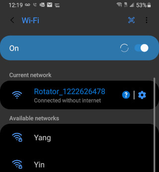
During startup the S.A.T. will try to connect to a WiFi network if one has been configured. If it cannot connect to a WiFi network then it will beep twice and start its internal WiFi Access Point. In this case the LCD will display an IP address of 192.168.4.1.
Connect to the S.A.T. Access Point
Using your mobile device*, search for available WiFi network. If the S.A.T. is in Access Point mode then an access point with the name CSN_SAT_XXXX will be available. The XXXX is the serial number of the S.A.T. (older firmware versions had an access point name of Rotator_XXXX).Connect your mobile device to that access point. (Some devices will complain that this access point will not provide internet access. This is normal and you should allow the connection if prompted.)
* Any device that supports Wifi and has a web browser will work such as cell phones, tablets, computers and laptops.
Open the Dashboard
Using your mobile device's web browser, navigate to the IP address displayed on the LCD screen. For example: http://192.168.4.1The S.A.T. dashboard will open on your device.
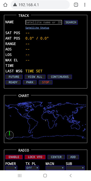
The S.A.T. Dashboard
The S.A.T. dashboard is seperated into four main areas.Track Panel
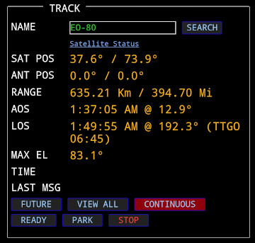
While tracking, this panel displays essential satellite information and current antenna position information. Current wind speed and direction is also displayed for your location.
Entering a satellite name or catalog number into the Name box and clicking Search will start tracking the entered satellite, if it's found in the loaded TLE file.
The Satellite Status link will open the Amsat Satellite Status Page in a new window .
The SatNOGS link will open the excellect SatNOGS map for the currently tracked satellite.
Available Buttons:
NEXT PASSES - Predict and display current and future passes.
VIEW ALL - View the entire set of satellites stored in the S.A.T.
CONTINUOUS - Continue tracking the selected satellite even after LOS. A green button indicates Continuous mode is active. A red button means Continous mode is not active.
SCHEDULE - Enable/Disable satellite schedule mode. See SCHEDULE section below for details.
READY - Move the antenna to the Ready position
PARK - Move the antenna to the Park position
ANT ENABLE - Enable or disable the rotator. Green to enable the rotator and red to disable. When disabled, no movement commands will be sent to the rotator.
STOP - Stop all movement and tracking
Map & Chart Panels
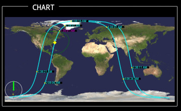
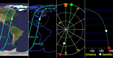
Worldmap
This is a full color map display. With this style of display you can see the satellite location above the Earth and it current track. In the lower left is a graphical display of the current antenna position.In the bottom right of the map is a little icon that will toggle the ground track display on and off when clicked.
Polar
The polar view takes some getting used to but contains a lot of useful information. The outer ring is horizon and the center is directly overhead. North is towards the top. This display shows the satellite track across the sky as well as the AOS and LOS azimuth and current antenna position. The color of the track indicates if the satellite is in sunlight or shadow - yellow for sunlight and green for shadow. The antenna indicator changes color if the rotator is in flipped/reverse mode - purple for reverse and orange for normal. You can click and drag in that view to rotate the North orientation.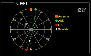
Ground View
This view simulates the observer standing on the ground and looking towards the satellite's current postion. A compass is displayed along the bottom to indicate direction. With this view you can follow a satellite as is rises above the horizon and travels across the sky until it sets. The track across the sky is displayed as well as the current antenna position. The color of the track indicates if the satellite is in sunlight or shadow - yellow for sunlight and green for shadow.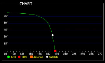
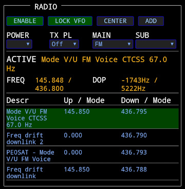
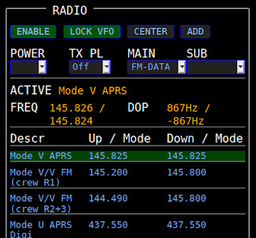
Radio Panel
Displays radio controls and available satellite transponders.Top Row Buttons:
ENABLE - Enable or disable rig control. A Green button means the rig is enabled and will be controlled. If red then it will not.
LOCK VFO - The S.A.T. keeps the uplink frequency in step with the downlink as you make changes with the VFO knob. Disabling this lets you tune the downlink without affecting the uplink. (Generally not needed if your radio has an RIT control).
CENTER - Sets the frequencies back to the transponder center frequencies. Basically resets any changes you have made by turning the dial.
ADD - Allows you to add a transponder that is not listed.
Below the buttons are the radio controls:
POWER - Sets the radio power.
TBW - Sets the transmit bandwidth.
TX PL - Sets the TX PL tome.
MAIN - Sets the MAIN band mode.
SUB - Sets the SUB band mode.
The next area show the details of the currently selected transponder. The transponder name, frequencies adjusted for doppler shift and curent doppler shifts are displayed.
Below the active area are the available transponders for the currently tracked satellite. Clicking on a transponder name will make it active and will configure the radio modes, if the modes are known. In the event that the SatNogs frequency is incorrect, you can change a frequency directly by clicking directly on it.
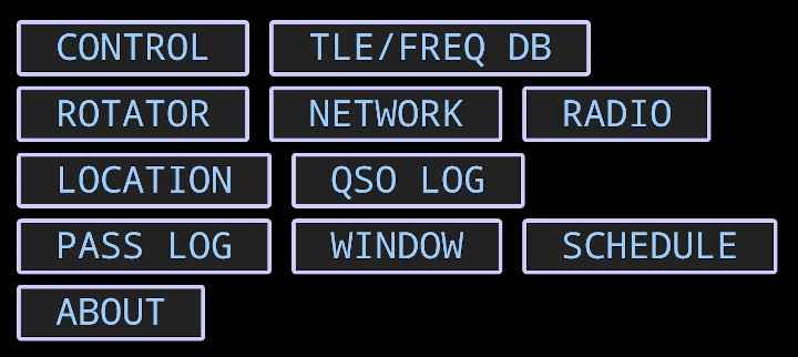
Option Buttons
On small screen devices such and phones and tablets the buttons will be found at the bottom of the page. On full size devices the button will location across the top of the page.The various options are described in detail below:
CONTROL - Manually control the rotator.
TLE/FREQ DB - Open TLE and transponder settings
ROTATOR - Open Rotator settings.
NETWORK - Open Network & WiFi settings.
RADIO - Open Radio settings.
LOCATION - Open Location, Grid square, Callsign, Time settings.
CALL LOG - Open the QSO log.
PASS LOG - Open the satellite pass log.
WINDOW - Open a secondary windows.
SCHEDULE - Open satellite schedule window.
ABOUT - Open About windows. Firmware updates.
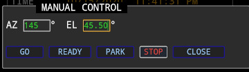
MANUAL CONTROL PANEL
The control panel lets you manually point your antenna to a given direction.Enter a grid square into POINT TO LOCATION field the have the AZ automatically calculated for you. Elevation is not changed with this feature.
PAN Section
On the right side of the panel are four pan buttons. Press and hold the buttons to move the appropriate axis. These work similar to the physical movement button on your rotator control box.
Up button - Move elevation up.
Down button - Move elevation down.
Left button - Move azimuth left (counter clockwise).
Right button - Move azimuth right (clockwise).
Buttons:
GO - Move to the entered position.
READY - Move the antenna to the Ready position.
PARK - Move the antenna to the Park position.
STOP - Stop all motion.
CLOSE - Close the manual control panel.
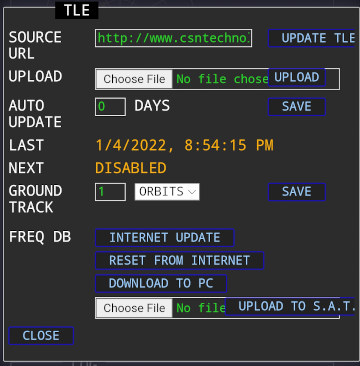
TLE/FREQ DB PANEL
The TLE Panel is where you set various TLE options.SOURCE URL - Provide an internet address of the TLE to download. Note that the S.A.T. does not support https:// addresses. You can usually simply remove the 's' from https and it will work but it depends on the server that you are connecting to. Click UPDATE NOW to update. Note that an internet connection is requires to update.
UPLOAD - Use this option to upload a custom TLE file. This file will replace the TLEs that are stored in the SAT. The uploaded TLE file should be in the standard format and must not contain any header lines.
AUTO UPDATE - How often to automatically update the TLEs from the SOURCE URL. Use zero to disable auto-updates.(Click SAVE to save setting)
LAST - The date and time of the last TLE update.
NEXT - The date and time of the next scheduled update if AUTO UPDATE has been set.
GROUND TRACK - How many hours of ground track should be shown on the maps. (Click SAVE to save setting)
FREQ DB - Options for refreshing the transponder database.
INTERNET UPDATE - Updates the transponder data while preserving changes you have made.
RESET FROM INTERNET - Factory resets the transponder database. Changes you have made will be lost.
DOWNLOAD TO PC - Downloads a text file of the transponders to your PC. We suggest you back up your frequency file to your PC after you make transponder changes.
UPLOAD TO SAT - Lets you choose a transponder file and upload it to the SAT.
CLOSE - Close the TLE Panel
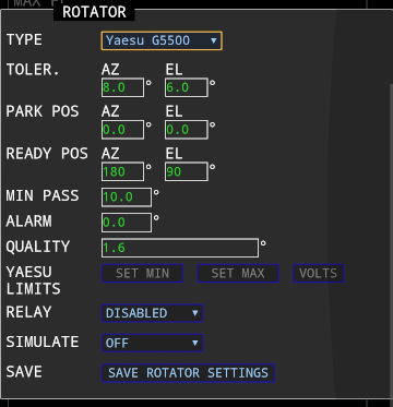
ROTATOR PANEL
The Rotator Panel is where you will find the rotator and satellite tracking settings:TYPE - Choose the rotator model to use. The S.A.T. natively supports the Yaesu G5500, G5400 and G5600 with the included cable. PstRotator is also supported.
IP ADDRESS - For PstRotator enter the IP address of the computer where PstRotator is running. PstRotator needs to be configured to accept UDP packets. In the PstRotator "Communication" menu choose "UDP Control Port." You can accept the default IP address and port in displayed in this window. If the settings are blank the click the "By Default" button. Click "Save Settings" to close the window. Finally, under the Settings menu in PstRotator, click "UDP Control" to allow remote control. Once configured properly, PstRotator will send feedback to your S.A.T. letting it know the antenna's current position. If you do not see the correct antenna postion displayed in the S.A.T., you may need to allow UDP port 12000 through your computer's firewall.
TOLERANCE - The S.A.T. tracks in such a way that when it moves the antenna it moves ahead of the satellite. This causes the satellite to pass directly in front of the antenna as the satellite moves across the sky and prevents the antenna from always having to "catch up" to the satellite. The TOLERANCE sets this window of movement. For example, with a setting of 10° for azimuth, when the satellite moves ahead of the antenna by 5° the antenna will move 5° ahead of the satellite. Then the satellite will then pass pass directly in front of the antenna and when it leads by 5° again, the antenna will move 5° ahead of it again. Same for elevation.
PARK POS - The position the antenna should move to when the Park button is pressed.
READY POS - The position the antenna should move to when the Ready button is pressed. For the fastest response when tracking, a Park position of 180° azimuth and 90° elevation should be used.
POST PASS - Choose how the antenna should be positioned at the end of a pass. You can choose to move to the Park or Ready position or no movement. Be aware this option may stress your rotator beyond the duty cycle limits specified in you rotator user manual.
MIN PASS - The minimum elevation a satellite must reach to be displayed when the NEXT PASSES button is pressed.
ALARM - The S.A.T. contains a built in beeper that will sound when the satellite reaches a set amount of time prior to AOS. Enter the minutes and seconds here at which time you would like to hear the alarm. Enter 00:00 to disable the alarm.
PLAY ALARM ON - The AOS alarm can be sounded on the S.A.T. using built in beeper, in the web browser or both. Note that not all web browers are supported.
QUALITY - This is a quality setting for the angle sense potentiometer in the rotator housing. If you hear excessive relay clicking in your rotator box you can slowly increase this value. A higher value reduces the resolution when the antenna is commanded to a particular position. For example if the setting is 2° here and the antenna is commanded to 100° it may stop anywhere between 98° and 102°.
YAESU LIMITS - (See the calibration procedure below)
RELAY - Enable the build in relay. Your S.A.T. has a three terminal relay jack. The center is common and the right and left sides are NO and NC respectively. When the relay option is enabled, the relay closes when the satellite reaches 3° below the horizon just before AOS and stays closed until LOS. Relay is rated 24 VAC, 2 Amps, total 48 Watts.
SIMULATE - If no antenna is connected then checking this option simulates one and the information panels and maps display where the would be if it was connected.
SAVE - Save and close the Rotator Panel
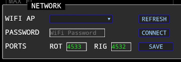
NETWORK PANEL
Connect your S.A.T. to the internet. The visible 2.4GHz WiFi points will be available in the dropdown box. If needed, click the REFRESH button to refresh the list. If you want to connect to a hidden WiFi network, please see the "Common Questions" section at the bottom of the page. Use the WiFi AP select box to choose an Access Point. Enter your WiFi password and click CONNECT. The S.A.T. will restart and attempt to connect to the WiFi network. Look at the LCD to see the IP address obtained and then connect to it using your mobile devices. Once connected you can update the TLEs and perform firmware updates.PORTS - Your S.A.T. is visible on the network as a HamLib compatible rotator and rig server. Use these fields to change the default listening ports. (See Advanced Settings below)
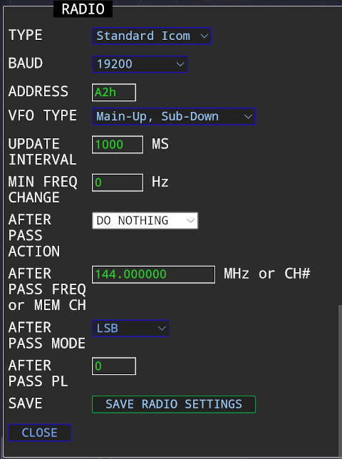
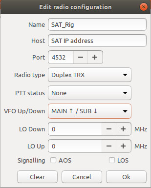
RADIO PANEL
Configure your Radio in this panelTYPE - Choose the type of radio to control. For most Icom radios, including the 9700, you can select 'Standard Icom'. If you have an Icom 820,821 or 910 then choose the "Icom 820H/821H/910H" selection. There is also a choice if you are using an Icom 7100. The S.A.T. works best with the Icom satellite radios - 9700, 9100, 910, 820 and 821. It will work with other Icom radios but your results will be limited since they are not full duplex. The Icom 705 is not supported since it does not have a CI-V port.
BAUD - Select the baud rate of your radio. This must match the baud rate setting on your radio. 19200 baud is recommended for radios that support it.
ADDRESS - The CI-V hexadecimal address of your radio. The Icom 9700 default address is A2h. The address in the S.A.T. must match the address in the radio.
VFO TYPE - The VFO type of your radio. The Icom 9700 is Main-Up / Sub-Down.
* Do not enable Satellite Mode on the Icom 9700
UPDATE INTERVAL - How often to send frequency updates to the radio. (In milliseconds)
MIN FREQ CHANGE - Minimum doppler correction in Hz before sending frequency updates to the radio.
AFTER PASS ACTION - Choose what you want your radio to do after a satellite pass. Options are Do nothing, Restore VFO which returns the state of the VFO to what it was prior to tracking, Set a Freq, or choose a memory or calling channel.
AFTER PASS FREQ OR MEM CH - If you choose Set Freq above, enter the full frequency here. If you choose Set Mem Ch# above then enter the memory channel here.
AFTER PASS MODE - If setting a frequency, you can also set the mode.
AFTER PASS PL - If setting a frequency, you can also set a PL tone.
SAVE - Save and close the Radio Panel
* Note that the SAT will utilize memory channel 99 if you choose 'Restore VFO' in the After Pass option. Any contents in memory channel 99 will be overwritten.
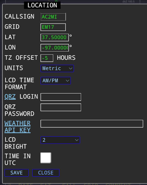
LOCATION PANEL
Enter operating location and other settings.CALLSIGN - Enter your callsign here to be used in the QSO logging feature.
GRID - Enter your gridsquare to automatically calculate your latitude and longitude. It's also used the the QSO logging feature.
LAT,LON - Enter your precise latitude and longitude.
USE GPS - Use the GPS to automatically fill in the Grid and location fields.
GPS ACTIVE - Enable the GPS for satellite tracking. (See the GPS section below).
TZ OFFSET - Enter your timezone offset from UTC in hours.
UNITS - Choose to display Imperial or Metric units.
QRZ LOGIN - Enter your QRZ.com login name (optional, used for the Call Log lookup feather)
QRZ PASSWORD - Enter your QRZ.com password (optional)
WEATHER API KEY - Enter your OpenWeatherMap account key (optional). Create a free account at OpenWeatherMap to obtain a key.
LCD BRIGHT - Adjust the brightness of the LCD screen. (For compatable units)
TIME FORMAT - Choose your preferred time display format.
QSO LOG TYPE - For automatic QSO log entry, choose your log software. See the QSO LOG section below for more details.
QSO LOG IP - Enter the IP and PORT where the log software is running.
PASS LOG
Click this button to display a history of the satellites that have been tracked and have risen above the horizon.WINDOW
This button will open a separate browser window that you can move to another monitor. A single item can be displayed such as the Map, one of the charts, general data, etc. There is no limit to the number of windows you can open. (Serves no purpose on mobile devices)SCHEDULE
You can schedule the satellites that you want to track. For example if you want to collect APRS packets from every pass of the ISS, even when you're not present, you can do that here.Choose a satellite and a transponder from the dropdown lists and click the ADD button. You can add any number of satellites this way. To remove a satellite, click the red X next to the name.
To enable the schedule, press the SCHEDULE button in the TRACK panel. A green button means the schedule is active and if red then it is not active.
With the schedule enabled the S.A.T. will track all the satellites in list in the order of AOS. Tracking starts about 60 seconds before AOS.
A satellite that is currently being tracked will never be interrupted by a scheduled satellite. So if you are manually tracking when a schedule pass is approaching your currently tracked satellite will not be stopped. Also, when two scheduled satellites overlap in time, the one with the earlier AOS will be tracked first and all the way to LOS before the next satellite in the schedule is selected and tracked.
ADD SAT - Add the currently selected satellite and transponder to the schedule.
CLEAR - Remove all satellites from the schedule.
LOAD - Load the saved schedule.
SAVE - Save the current schedule.
CLOSE - Close the window.
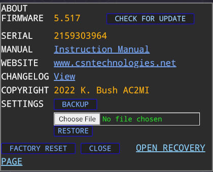
ABOUT PANEL
The About panel display firmware versions and copyright information. Click the CHECK FOR UPDATE button next to the firmware version to check for updates (Internet connection is required).*PLEASE CHECK THE CHANGELOG FOR ANY SPECIAL INSTRUCTIONS BEFORE PERFORMING AN UPDATE.
The FACTORY RESET button clears all settings and reboots the device.
You can backup your settings by clicking the BACKUP button. You can restore your settings by choosing a saved settings file and clicking the RESTORE button.
Rotator Calibration
Before attaching your S.A.T. to your rotator, manually set the azimuth and elevation their minimums. On the G5500 this is 0° AZ and 0° EL, on the G5400 this is 180° AZ with the needle to the left and 0° EL.
You can now attach the S.A.T. to your rotator using the supplied DIN cable.
Once connected, open the ROTATOR PANEL in the Dashboard.
Once connected, open the ROTATOR PANEL in the Dashboard.
Automatic Calibration
Your S.A.T. can swing the antenna rotator through it's full rotations in both Azimuth and Elevation to detect the limits. Make sure your rotator is ready to move through the full rotation and nothing is obstructing it's motion such as short wires, tree branches, etc. Once the calibration is started the only way to stop it is to remove power from the S.A.T.
Press the AUTO CAL button in the opened ROTATOR PANEL. When you press OK on the warning box the rotator will start moving. This can take up to four minutes. While it's calibrating you can watch the guages on the Yaesu control box. When it's complete a box will notify you that the calibration is complete. You can skip the Manual Calibration below.
If, however, a box opens and indicates that voltages were exceeded then please follow the Manual Calibration procedure below.
*Note: Not all rotator choices support auto-calibration.

Manual Calibration
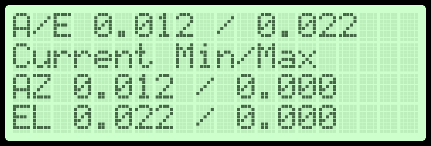
Now click on the VOLTS button (You can close the message that opens, it's just a reminder of these instructions). The sensed voltage from the rotator control box is now displayed on the LCD.
Manually increase your azimuth and watch the voltage on the LCD. The first number on the top line is the voltage for azimuth. Stop moving if this voltage goes higher than 5 volts! If it passes 5 volts then you need to turn the Output Voltage Adjustment knob on the back of your rotator control box to decrease it. See your Yaesu Manual for instructions.
The goal is to increase the AZ to it's maximum and adjust the voltage to keep it between 4 and 5 volts. The maximum azimuth for the G5500 is the red 90° mark on the right side of the guage, on the G5400 the maximum is the 180° on the right of the guage. If the voltage ends up below 4 volts then for highest accuracy you should increase it by turning the Output Voltage Adjustment on the back of your rotator control box. When the voltage is between 4 and 5 volts at the maximum azimuth then you can move on to the elevation setting.
The elevation is set the same way as the azimuth. Increase the elevation and watch the LCD to make sure it does not pass 5 volts. Again adjust the voltage to get it between 4 and 5 volts at the maximum elevation (180° on both the G5400 and G5500). *If your G5500 is limited to only 90 degrees elevation then choose "Yaesu G5500 360/90" in the rotator selection. Then during the manual calibration you can move the elevation to 90 degrees instead of the full 180.
Finally, when the both azimuth and elevation are at their maximum positions and the voltages are between 4 and 5 volts, press the SET MAX button.
Now move both AZ and El all the way back to the minimums. Press the SET MIN button.
Your S.A.T. is now calibrated to your rotator control box. Press the STOP button to exit Voltage mode. You need to do this calibration process every time the S.A.T. boots. Just kidding! *The calibration only has to be done once ;).
* Note that if anything changes in your rotator configuration, such as changing the rotator cables, you should calibrate the S.A.T. again.

Using your S.A.T.
Start Tracking
Be sure to configure your Location, Rotator and Radio using the instructions above before using your S.A.T. Of course, make sure your TLE's are up to date for best results.There are a few ways to start tracking a satellite. The quickest is to type the name or catalog number into the search field and click SEARCH. The search field is not case sensitive and if you use a name it must match the name as it is in the TLE file. You can enter a partial name, for example entering "IS" would find and track "ISS". If you enter a partial name then the first matching satellite will be selected. Entering "AO-9" might find "AO-91" or "AO-92". If you know the catalog number then that is the most accurate way to search.
Another way is to click the "VIEW ALL" button. This will display a list off all the satellites in the loaded TLE file. Simply click a satellite name to start tracking.
Click the little report icon next to the satellite name in the 'View All' page to generate a printable pass prediction report for that individual satellite. The REPORT FOR SELECTED button at the bottom of the page will generate a pass prediction report for all satellites that have been checked. The report will be generated in chronological order.
Finally, clicking "NEXT PASSES" will display a list of satellites that are currently up in the sky and those that are coming up next. Those that are green are already up and the orange are currently below the horizon but they are the next to rise. The brightness of the boxes indicates the relative maximum elevation, brighter being higher. Satellites that will not rise above the MISS PASS setting in the rotator page will not be displayed. Click a satellite name to start tracking.
While Tracking
While tracking the page will automatically update about every 2 seconds. The S.A.T. will automatically determine if it should flip the antenna to track the satellite continuously through it's pass. (REVERSE) will be displayed in the antenna position line to indicate this.The maps and graphs will also start updating. Click anywhere on a map or graph to switch to the next display type. Radio tips
Connection GPredict, etc

Using your Radio
* If your radio supports both VFO mode and SATELLITE mode, always use VFO mode. Do not use SATELLITE mode on your radio. For the Icom 9700, and radios that support it, display both VFOs on the screen at the same time. The red TX icon will be above the top VFO. If the red TX icon is on the bottom VFO then you are in satellite mode and you should change to VFO mode.
Some radios have a spectrum scope. If you wish to see the received signals on the scope be sure to attach the scode to the receive VFO. (See radio manual for instructions)
* In order to use the PL Tone properly on your Icom, ensure the following setting is set to ON (DUP)
Menu -> Set -> Function -> Auto Repeater
When tracking starts the first transponder in the list is automatically selected. Your radios VFOs and modes will be set up and the center frequencies will be selected, adjusted for doppler. Tuning will start. The calculated doppler offset and current frequency will be display in the RADIO area on the page.
Click on a transponder name to switch to it - the radio bands and modes will be automatically set for the selected transponder and frequency updates will start. If a frequency is not correct in the transponder list you can click on it and change it. The frequency you enter will be the new center frequency that the doppler shift is calculated from. The setting is not saved however you can contact us and we will make the necessary adjustment in the transponder database. If a mode is not selected correctly you can chage it using the drop down menus. Again, contact us and we'll make corrections in the database.
The POWER and TX PL selections let you change the transmit power and transmit PL tone respectivly. Note that not all radios support changing the power levels with remote commands.
Satellite frequencies drift. This can be caused by thermal issues on the spacecraft, from satellite age and/or other factors. So some adjustment may be required by operators on on the ground. The easiest way is to use the RIT control on radios that have it (Icom 9100 & 9700). You can use the RIT control to fine tune the downlink frequency.
The other way is to simply move the tuning dial on the radio but in this case you must be aware of the LOCK VFO option on the S.A.T.
With the VFOs locked, any change you make to the downlink will also be reflected in the uplink frequency. For example, if you tune the downlink down by 5kHz, the uplink will tune up by 5kHz. Unlocking the VFO's prevents this and you are free to change the downlink without affecting the uplink.
Keep in mind some features of the radio may be difficult to manipulate while frequency updates are being sent by the S.A.T., especially if the update interval is fast (less than 1 sec). Clicking the ENABLE button will stop the updates and the button will turn red. You are now free to adjust the radio and when ready you click ENABLE to start the updates again.
BEST PRACTICE
For the easiest operation follow the steps below. This is tailored for the linear satellites but partly apply to the FM ones also.
For best result using the RIT set your radio to not display the 1Hz digit. With the 1Hz showing you'll have rotate the RIT much more than if that digit is off. To turn the 1Hz digit off press and hold the digit for at least one second.
1. Choose a satellite and transponder.
2. Tune your RIT knob on the radio until you hear your self. You should only have to move the RIT within a couple KC to find yourself. Do not touch the tuning knob until you find yourself.
3. One you can hear yourself you can then use the radio's tuning knob to work your way up and down the passband.
That should be it!
Adding and Editing Transponders
You can add new transponders to satellites by clicking on the Add button. You can also edit existing transponders by clicking on frequency itself in the transponder list. Each one will open the transponder edit window show at the right.
DESCRIPTION - Enter a transponder description (up to 30 characters).
FREQ UP - Enter the uplink frequency in megahertz.
MODE UP - Enter the uplink mode.
PL UP - If the satellite requires a PL, enter it here.
FREQ DOWN - Enter the downlink frequency in megahertz.
MODE DOWN - Enter the downlink mode.
RIT - Enter a RIT offset in kilohertz. You can use a '-' minus symbol to enter a negative offset.
If you check the box next to APPLY RIT TO ALL TRANSPONDERS then the RIT setting on this transponder will also apply to all the other transponders on this satellite.
REMOVE TRANSPONDER - Removes the transponder from this satellite.
SAVE - Saves your changes and closed the edit box.
CLOSE - Closes the edit box without saving changes.
Advanced Features
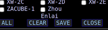
Favorites List
Usually the standard TLEs from the internet contain far more satellites than you're interested in. More satellites equals more time to search and more time to predict future passes.In the VIEW ALL page, each satellite has a checkbox next to it. Check of each satellite you are interested in and click SAVE at the bottom. Now only those satellites that you've selected will be considered when you search and predict future passes. This greatly improves performance.
Note that having no satellites is the same and including them all.
Custom TLE Files
Instead of using a URL as a source of TLEs you can instead upload a file. The file must be a standard ASCII TLE text file and must not contain any headers such as comments or other fluff, eg. it must start with a satellite name. The uploaded file will replace any stored TLEs. The favorites option will work with a custom TLE.Auto Update TLE
If enabled, the S.A.T. will automatically download a copy of the TLEs from the same url that they were last downloaded from. TLEs will only be downloaded while the S.A.T. is idle. It's also going to check exactly the number of days you enter. If you last downloaded TLEs on Oct 1st at 9am, then it will try on Oct 3rd at 9am. If the S.A.T. is not idle at that exact time it will try when it becomes idle.You cannot use the custom TLE function with automatic updates. Be sure to disable the automatic updates by entering a zero in the AUTO UPDATE field.
QSO LOG w/ ADIF EXPORT
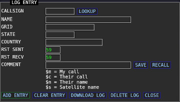
Your S.A.T. contains a call log feature with internet lookups and macros.Press the CALL LOG button at the bottom of the page to open the call log entry window. If you have set your QRZ login credentials in the LOCATION page then you can use the LOOKUP button to automatically fill in the log entry fields. (You must be a paid QRZ subscriber for this to work.)
Fields such as Date, Time, Satellite Name, Frequency, Mode, etc. are automatically filled using the currently selected satellite and transponder.
The Comment field supports 'replacement' macros and can be saved between sessions. For example if you often have a comment such as "Thanks KC2SYF for the RS-44 contact." you do not need to type it in every time. Simply enter a comment as "Thanks $c for the $s contact." The '$c' will be replace with the call sign of the contact and the '$s' will be replace with the current satellite name. The legend for the available replacement types can be found below the comment field.
The call log entries are displayed in the lower part of the page, above the bottom row of buttons.
You can download your log entries in ADI format with the DOWNLOAD button. The file will be saved with a unique file name wherever your brower places Downloaded files. The QSO log is saved on the S.A.T. between power cycles but it only holds 100 entries and should be downloaded frequently since they only exist on the device and are not backed up.
If the transponder has "FT4" in the name then the ADIF file will export with Mode=MFSK and Submode=FT4.
Buttons:
ADD ENTRY - Store the current entry into log.
CLEAR ENTRY - Clear the entry fields.
DOWNLOAD LOG - Download the stored log in ADI format.
DELETE LOG - Delete the stored log.
The S.A.T. can also send log entries to many desktop logging programs. DX Keeper, Ham Radio Deluxe, Log4OM and N1MM. If your logger accepts ADIF records over TCP or UDP it may also work. Remember to set the IP address and port of your logging software in the LOCATION settings page in your S.A.T.
Log Software Setup Instructions
DX Keeper - Press the Config button and select the Defaults tab. In the Network Service area you can set the port. The default port is 52000 and this causes DX Keeper to listen on port 52001 for ADIF records. So if you use 52000 in DXKeeper then enter port 52001 in the S.A.T.Ham Radio Deluxe - In the HRD Logbook program press the Options button and select QSO Forwarding. In the UDP Receive section check the Receive QSO notification button and select the Defaults tab. Choose a port and database to receive QSO records.
N1MM - From the Config menu choose Configure Ports, Mode Control, etc. In the Configure box that opens, select the WSJT/JTDX Setup tab. In the upper WSJT-X section check the enable button. Choose a port to received log entries. The IP address can be ignored.
Log4OM - Open the configuration panel and choose Connections from the tree on the left. Now on the right side, click UDP. Under the Inbound section, enter a port and a connection name (eg SAT). In ther Service Type field choose ADIF_MESSAGE. Finally click the green plus button to complete the setup.
Amateur Contact Log (AC Log) - Under the Settings menu in ACLog, choose Application Programming Interface. Enable the TCP API Server option and set a port number, the default of 1100 is fine. Then click Done and restart ACLog. In the Location panel in the S.A.T., choose ACLog, enter the IP address for the computer running ACLog and enter the port that ACLog is listening on. (Ensure you are running version 7.0.4.4 or later of ACLog). (Also, thank you to N3FJP for making this happen)
Continuous Tracking
When a satellite sets below the horizon the S.A.T. normally stops tracking (at -2° elevation) the satellite and enters idle mode. This is a safety feature to prevent unintended movement of the rotator. If however, you want to keep tracking you can click the CONTINUOUS button. The button will change to green when enabled. Now when a satellite sets, a new AOS and LOS is calculated and the antenna will move when the satellite reaches AOS. Use caution with this setting since your rotator will move again when the satellite reaches AOS.

Rotator & Rig Server
Your S.A.T. is also and Hamlib compatible rotator and rig control server. In this way you can continue to use your favorite satellite tracking program in lieu of the built in tracking of the S.A.T. (This feature has only been tested with GPredict)In GPredict you can set up the rotator and rig in the interfaces section. The standard ports are enabled by default on the S.A.T., 4533 for the rotator and 4532 for rig. Note that PTT is not yet supported. When tracking with a PC program do not simultaneously track with the S.A.T., confusion will ensue!
GPS Operation
If your S.A.T. is equipped with a GPS then the status panel will include a line to show the status of the GPS and a few GPS related option will be available in the Location settings page.
In the Location settings you can set the GPS ACTIVE option to one of three settings:
DISABLED - The GPS will not be used for satellite tracking purposes and the grid and coordinates you enter in the Location settings will be used.
ENABLED - The GPS will be used for tracking purposes.
ENABLED w/ AUTO GRID MODE - The GPS will be used for tracking purposes and 2 minutes after the S.A.T. is powered up the LCD will change to Grid Mode (described below).
If the GPS is set to ENABLED but it has not yet acquired a position lock the the corrdinates you enter in the Location tab will be used. Once a lock is acquired the GPS will be used.
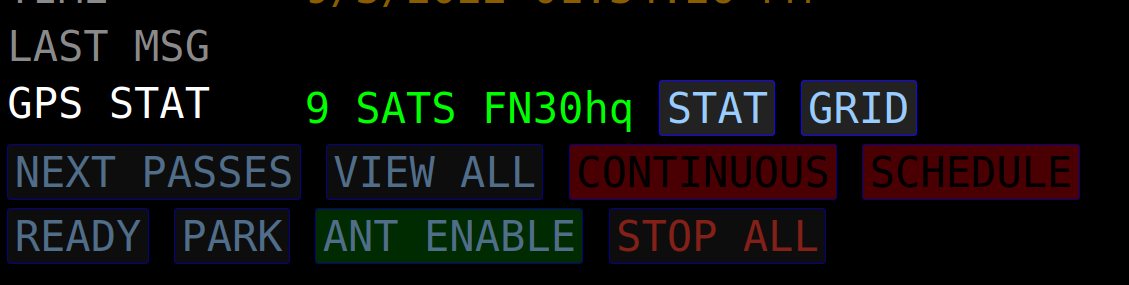
The number of GPS satellites acquired and current grid are displayed on the GPS STAT line in the TRACK panel. The colors have meaning:
GREEN - The GPS is locked and enabled - The GPS will be used for tracking.
RED - The GPS is either not locked or not enabled - The GPS will not be used for tracking.
In the GPS status line there is a button labeled GRID. This button starts and stops Grid Tracking mode. When enabled the LCD of the S.A.T. changes to show current time, grid, acquired satellites, lattitude and longitude. When moving from oen grid to another the S.A.T. will beep three times to let you know that you have crossed a grid boundary. (A six character grid is displayed but the alarm sounds when crossing 4 character grid boundaries).
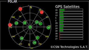
The STAT button will change the POLAR view to a GPS satellite view. The GPS satellite positions and signal strength will be displayed. Press STAT again to put the POLAR view back to normal.
If your S.A.T. is equipped with a GPS then the status panel will include a line to show the status of the GPS and a few GPS related option will be available in the Location settings page.
In the Location settings you can set the GPS ACTIVE option to one of three settings:
DISABLED - The GPS will not be used for satellite tracking purposes and the grid and coordinates you enter in the Location settings will be used.
ENABLED - The GPS will be used for tracking purposes.
ENABLED w/ AUTO GRID MODE - The GPS will be used for tracking purposes and 2 minutes after the S.A.T. is powered up the LCD will change to Grid Mode (described below).
If the GPS is set to ENABLED but it has not yet acquired a position lock the the corrdinates you enter in the Location tab will be used. Once a lock is acquired the GPS will be used.
The number of GPS satellites acquired and current grid are displayed on the GPS STAT line in the TRACK panel. The colors have meaning:
GREEN - The GPS is locked and enabled - The GPS will be used for tracking.
RED - The GPS is either not locked or not enabled - The GPS will not be used for tracking.
In the GPS status line there is a button labeled GRID. This button starts and stops Grid Tracking mode. When enabled the LCD of the S.A.T. changes to show current time, grid, acquired satellites, lattitude and longitude. When moving from oen grid to another the S.A.T. will beep three times to let you know that you have crossed a grid boundary. (A six character grid is displayed but the alarm sounds when crossing 4 character grid boundaries).
The STAT button will change the POLAR view to a GPS satellite view. The GPS satellite positions and signal strength will be displayed. Press STAT again to put the POLAR view back to normal.
Common Questions / Troubleshooting
I'm locked out of my S.A.T.!
If you've forgotten your password, you can reset it by appending your serial number to the URL you use to access the S.A.T. web interface.
For example, if your serial number is '123456' then the URL is: http://your ip address/123456
If you've forgotten your password, you can reset it by appending your serial number to the URL you use to access the S.A.T. web interface.
For example, if your serial number is '123456' then the URL is: http://your ip address/123456
The S.A.T. is much slower than normal.
The S.A.T. is having trouble communicating with your radio. Check all connections and radio settings (address & baud). If you do not have a radio attached ensure that the radio type is set to NONE in the radio settings panel.
The S.A.T. is having trouble communicating with your radio. Check all connections and radio settings (address & baud). If you do not have a radio attached ensure that the radio type is set to NONE in the radio settings panel.
How do I connect to a hidden WiFi network?
First connect to the Access Point of S.A.T. as described above. Once connected enter the following into the browser address bar:
http://192.168.4.1/?a=W|APNAME|password
Replace APNAME with the name of the hidden WiFi network and password with the password for the network.
Once entered, your S.A.T. will reboot and should connect to the hidden WiFi network.
What's in the box?
You should receive the S.A.T. device along with Micro-USB power cable, Rotator DIN cable, and a TRS cable to interface with Icom radios. A Micro-USB power adapter is not included.
You should receive the S.A.T. device along with Micro-USB power cable, Rotator DIN cable, and a TRS cable to interface with Icom radios. A Micro-USB power adapter is not included.
How is the clock set?
The clock on the S.A.T. is set automatically by the web browser that opens the S.A.T. dashboard. You can choose from various time display settings in the LOCATION panel.
The clock on the S.A.T. is set automatically by the web browser that opens the S.A.T. dashboard. You can choose from various time display settings in the LOCATION panel.
I get an error why I download TLEs
First make sure that the S.A.T. is not in access point mode and is connected to a WiFi network that has internet access. When in access point mode the IP address on the LCD will be 192.168.4.1 and there will be a WiFi network available on your mobile device with the name 'CSN_SAT_XXXX' where XXXX is the SAT serial number.
The S.A.T. does not support https addresses for the TLE url (note the 's' at the end of 'http'). Usually you can simply remove the 's' from the address and try again. If it still doesn't work, and you need to have that list, you'll have to download it to your device. Then you can upload it using the "Custom TLE Files" procedure described above.
The following TLE sources and know to work well:
AMSAT nasabare.txt (updated weekly)
http://www.amsat.org/tle/current/nasabare.txt
CSN nasabare.txt (a copy of AMSATs nasabare.txt) -
http://www.csntechnologies.net/SAT/nasabare.txt
CSN csnbare.txt (same satellites as nasabare.txt but generated with Celestrack data, updated daily) -
http://www.csntechnologies.net/SAT/csnbare.txt
How do I factory reset?
You can find the Factory Reset button in the About box in the web interface.
Another way to factory reset is remove power from the SAT and short the CI-V cable contacts with aluminum foil. When the SAT is powered up with the cable shorted it will enter reset mode. You will then have two opportunities to release the short, depending of what type of reset you want. Watch the SAT's LCD and after a few seconds it will tell that if you release the short it will reset the WiFi. If you keep holding the short it will then tell you if you release that it do a full factory reset. When finished it will ask you to reboot the SAT which you can do by removing the USB power plug, waiting a couple of seconds, then reinsert it.
QRZ Lookups Are Not Working
Various web browser plugings may be preventing the S.A.T. from accessing the QRZ.com. Try disabling these plugins or adding exceptions if possible.
Various web browser plugings may be preventing the S.A.T. from accessing the QRZ.com. Try disabling these plugins or adding exceptions if possible.
I cant connect the S.A.T. to my WiFi network!
The S.A.T. can only connect to 2.4Ghz networks. The S.A.T. searches for available access points when NETWORK panel is opened and also when the REFRESH button is clicked. Allow a few seconds for the search to complete. The discovered networks are then displayed in the WIFI AP selection box.
Not being able to connect is usually caused by not having the correct WiFi password. Check the 2.4G password in your router settings, sometimes it is not the same as the 5G one.
We found that there is a setting in xFinity access points that can prevent it from connecting. Find and uncheck the 'Prefer private Connections' setting in your routers configuration.
Also make sure that your access point if not filtering by MAC address for new connections.
Ubiquity networks - If you have slow performance or difficuly connecting you may need to enable Legacy Wireless Mode. Please consult your devices documentation for more information.
Starlink Wifi - Try seperating the 5G and 2.4G networks in you Starlink settings.
What are the recommended settings for the Icom 7100?
The correct settings for the 7100 are "Icom 7100" for radio type, 19200 Baud and VFO A-UP/VFO B-DOWN.
Icom's default CI-V address for the 7100 is 88h.
We recommend that you change the baud rate in the radio from AUTO to 19200 and turn off CI-V Transceive.
The correct settings for the 7100 are "Icom 7100" for radio type, 19200 Baud and VFO A-UP/VFO B-DOWN.
Icom's default CI-V address for the 7100 is 88h.
We recommend that you change the baud rate in the radio from AUTO to 19200 and turn off CI-V Transceive.
What are the recommended settings for the Icom 910/970?
Our users have found that 19200 baud, "Main Up/Sub Down" and an update interval of 200ms work well. Like other radios, it should not be in Sat mode. You cannot use the RIT on these radios since it only controls the top VFO which is the uplink. Instead, when tracking a linear satellite, you can Unlock the VFOs on the SAT and find yourself using the radio's VFO knob. Once you hear yourself clearly, you can re-lock the VFO's and move up and down the band with the VFO knob and the SAT will keep everything in sync and adjusted for doppler.
Our users have found that 19200 baud, "Main Up/Sub Down" and an update interval of 200ms work well. Like other radios, it should not be in Sat mode. You cannot use the RIT on these radios since it only controls the top VFO which is the uplink. Instead, when tracking a linear satellite, you can Unlock the VFOs on the SAT and find yourself using the radio's VFO knob. Once you hear yourself clearly, you can re-lock the VFO's and move up and down the band with the VFO knob and the SAT will keep everything in sync and adjusted for doppler.